
Measurement is the backbone of every technical and scientific process. Whether it is the diameter of a thin wire, the thickness of a metal sheet, or the precision of a machined component, accuracy in measurement determines the success of the final product. Among the many measuring tools developed to ensure such precision, the micrometer holds a unique and vital place. It is a finely crafted mechanical instrument designed to measure small dimensions with remarkable accuracy, usually in the range of 0.01 mm or even 0.001 mm.
The micrometer is not merely a tool—it represents centuries of human effort to improve the precision of manufacturing and science. It is often called a screw gauge, because its working principle depends on the movement of a finely threaded screw. The design is elegant yet powerful: by converting small rotational movements into linear motion, the micrometer allows extremely precise measurement of dimensions.
In this detailed article, we will explore everything about the micrometer—its construction, working principle, types, uses, calibration, maintenance, advantages, limitations, and industrial applications. We will also examine its evolution from mechanical forms to modern digital micrometers, highlighting its continuing relevance in an age of automation and smart measurement systems.
Historical Background of the Micrometer
The roots of the micrometer go back several centuries. The word itself is derived from the Greek words “mikros” (meaning small) and “metron” (meaning measure). The idea of using a screw for precise movement was first explored during the 17th century.
In 1640, an English scientist named William Gascoigne used a screw mechanism to measure the distance between stars through a telescope. His instrument, though not a micrometer in the modern sense, introduced the concept of the precision screw for accurate measurement. Later, in 1848, the French engineer Jean Laurent Palmer developed the hand-held micrometer screw gauge, which closely resembles the modern design used today.
Since then, the micrometer has evolved through continuous improvement in materials, design, and precision. The basic mechanical principle remains unchanged, but the methods of reading and accuracy levels have advanced drastically. Today, micrometers are available in mechanical, vernier, dial, and digital forms, serving industries from manufacturing to aerospace.
Basic Principle of the Micrometer
At its heart, the micrometer operates on the screw and nut principle. This principle converts small rotational movements into precisely controlled linear motion. When a screw of known pitch is rotated through one full turn, it moves axially by a distance equal to its pitch. By calibrating this movement with a scale, extremely fine measurements can be made.
The relationship is simple: Linear Movement=Pitch of Screw×Number of Turns\text{Linear Movement} = \text{Pitch of Screw} \times \text{Number of Turns}Linear Movement=Pitch of Screw×Number of Turns
For instance, if a micrometer screw has a pitch of 0.5 mm, then one complete revolution of the thimble moves the spindle forward or backward by 0.5 mm. The thimble is further divided into equal parts (usually 50 or 100 divisions), which allows measurement of a fraction of the pitch—thus achieving readings as fine as 0.01 mm (10 microns) or better.
This conversion of rotational to linear motion forms the foundation of the micrometer’s precision. The system is stable, self-locking, and insensitive to small external forces, which makes it ideal for accurate measurement of small dimensions.
Construction and Parts of a Micrometer
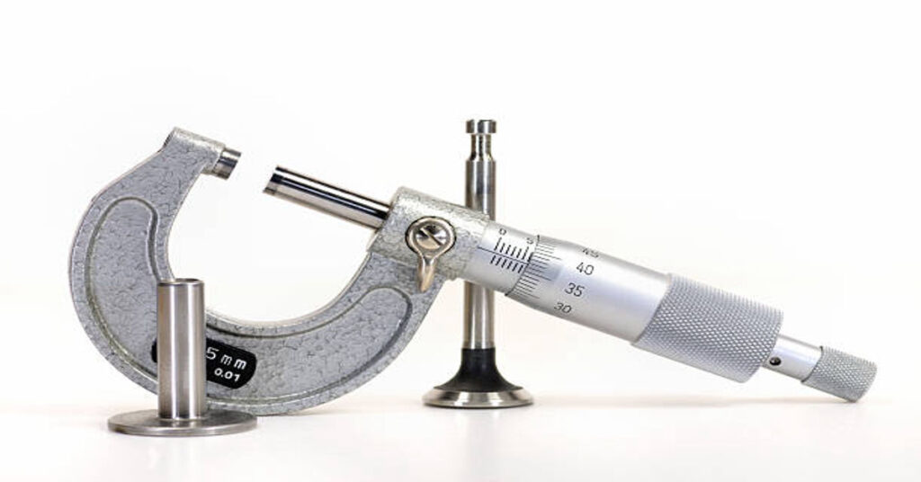
A typical outside micrometer—the most commonly used type—consists of several carefully engineered components that work together to achieve precise measurement.
Main Parts of a Micrometer
| Part Name | Function/Description |
|---|---|
| Frame | The C-shaped body that holds all parts together. It is rigid, stable, and designed to minimize thermal expansion. |
| Anvil | The fixed measuring surface against which the object rests. |
| Spindle | The movable part that advances or retracts through the screw mechanism to contact the object being measured. |
| Sleeve (or Barrel) | The stationary cylindrical portion carrying the main scale marked in millimeters or inches. |
| Thimble | A rotating cylindrical component attached to the spindle. It carries a circular scale (usually 50 or 100 divisions). |
| Ratchet Stop | A small mechanism at the end of the thimble that applies uniform measuring force, preventing over-tightening. |
| Lock Nut (or Locking Lever) | Used to lock the spindle in position after taking the measurement, ensuring the reading remains fixed. |
| Carbide Measuring Faces | Modern micrometers often have carbide-tipped anvils and spindles to resist wear and maintain accuracy. |
Working Principle Explained with Example
Let us assume a micrometer with a pitch of 0.5 mm and 50 divisions on the thimble scale.
Hence, each division represents: 0.550=0.01 mm\frac{0.5}{50} = 0.01 \text{ mm}500.5=0.01 mm
If the reading on the main scale (sleeve) is 5.5 mm and the thimble shows 22 divisions, then: Total Reading=5.5+(22×0.01)=5.5+0.22=5.72 mm\text{Total Reading} = 5.5 + (22 \times 0.01) = 5.5 + 0.22 = 5.72 \text{ mm}Total Reading=5.5+(22×0.01)=5.5+0.22=5.72 mm
Thus, the measured dimension of the object is 5.72 mm.
Types of Micrometers
Micrometers are classified according to their purpose, construction, and reading method. Below are the major types used in workshops and laboratories.
1. Outside Micrometer
This is the most common type used to measure the external dimensions (like diameter or thickness) of solid objects such as wires, rods, and plates. The object is held between the anvil and spindle, and readings are taken using the sleeve and thimble scales.
2. Inside Micrometer
Used to measure internal dimensions such as the diameter of a hole, bore, or cylinder. It often includes extension rods of varying lengths to measure different internal sizes.
3. Depth Micrometer
This type measures the depth of slots, holes, steps, or recesses. The base of the instrument rests on the surface, and the spindle moves downward to measure the depth.
4. Vernier Micrometer
Incorporates a vernier scale on the sleeve for readings more precise than 0.01 mm—often reaching 0.001 mm accuracy. The vernier scale allows fine interpolation between the main and thimble divisions.
5. Digital Micrometer
A modern version equipped with an electronic display that shows measurements directly in digital form. These devices reduce reading errors and may offer data storage or USB connectivity for data transfer.
6. Screw Thread Micrometer
Specially designed for measuring the effective diameter of screw threads. It uses interchangeable anvils shaped to fit the thread form accurately.
7. Sheet Metal Micrometer
A variant with a deep frame and a smaller anvil, designed to measure the thickness of sheets or foils without deforming them.
Table: Comparison of Micrometer Types
| Type | Measurement Range | Accuracy (Typical) | Main Use |
|---|---|---|---|
| Outside Micrometer | 0–25 mm, 25–50 mm, etc. | ±0.01 mm | External dimensions |
| Inside Micrometer | 5–500 mm (with extensions) | ±0.01 mm | Internal diameter |
| Depth Micrometer | 0–300 mm | ±0.01 mm | Depth of slots/holes |
| Vernier Micrometer | 0–25 mm | ±0.001 mm | High-precision work |
| Digital Micrometer | 0–100 mm | ±0.001 mm | Fast, error-free reading |
| Thread Micrometer | Variable | ±0.005 mm | Screw thread measurement |
Range and Least Count
The range of a micrometer refers to the maximum and minimum measurable sizes. Standard mechanical micrometers are available in ranges of 0–25 mm, 25–50 mm, 50–75 mm, and so on.
The least count is the smallest measurement that the micrometer can read. It depends on the screw pitch and number of thimble divisions. Least Count=PitchNo. of Divisions on Thimble\text{Least Count} = \frac{\text{Pitch}}{\text{No. of Divisions on Thimble}}Least Count=No. of Divisions on ThimblePitch
Example:
Pitch = 0.5 mm; Thimble divisions = 50
Least Count = 0.5 ÷ 50 = 0.01 mm
This means that every smallest division on the thimble represents 0.01 mm. Some precision micrometers, such as vernier or digital types, achieve a least count as small as 0.001 mm.
Procedure for Measurement Using a Micrometer
To achieve accurate results, the micrometer must be used with proper technique and care. Below are the recommended steps:
- Clean the Micrometer and Workpiece: Ensure that both the anvil and spindle faces, as well as the object, are free from dust, oil, and debris. Even a small particle can introduce error.
- Check Zero Error: Close the spindle gently until it touches the anvil. The zero mark on the thimble should coincide with the reference line on the sleeve. If not, note the zero error and apply correction later.
- Place the Object: Insert the object between the anvil and spindle. Hold it firmly but avoid pressure.
- Rotate the Thimble: Turn it gently until the spindle contacts the workpiece. Use the ratchet stop to ensure consistent measuring force.
- Lock the Spindle: Use the lock nut to hold the spindle in position, then remove the micrometer for easy reading.
- Read the Scales: Note the main scale reading and add the thimble reading. Apply zero error correction if necessary.
- Record the Measurement: Write down the final value with correct units and details.
Sources of Error and Precautions
Even though micrometers are highly precise, errors may arise due to incorrect handling, temperature changes, wear, or calibration issues. Recognizing and minimizing these sources is crucial.
| Source of Error | Description | Preventive Measures |
|---|---|---|
| Zero Error | Misalignment between thimble zero and sleeve reference | Check before use and correct mathematically |
| Parallax Error | Wrong viewing angle while reading scales | Read directly at eye level |
| Temperature Variation | Expansion or contraction of materials | Perform measurement at 20°C (standard) |
| Dirt or Burrs | Foreign particles between anvil and workpiece | Clean both surfaces properly |
| Excessive Force | Deformation of soft materials due to over-tightening | Use ratchet stop to apply uniform pressure |
| Wear and Tear | Worn screw threads or faces | Regular calibration and maintenance |
Calibration of a Micrometer
Calibration ensures that the micrometer gives true readings over time. It is typically performed using gauge blocks (slip gauges)—precision-made standards of known size.
Steps for Calibration
- Clean the micrometer and gauge blocks.
- Check zero setting by closing the spindle on the anvil. Adjust if necessary using the small wrench provided.
- Insert the gauge block between anvil and spindle.
- Read the micrometer and compare with the actual dimension of the gauge block.
- Record the difference as the calibration error.
- Repeat for several gauge block sizes across the micrometer’s range.
If errors exceed permissible limits (as specified by ISO or manufacturer standards), the instrument must be adjusted or serviced.
Advantages of Micrometer
- High Accuracy: Can measure up to 0.001 mm depending on type.
- Reliability: The screw mechanism ensures consistent results.
- Compact and Portable: Small enough to be carried in a pocket yet precise.
- Ease of Use: Simple to operate with minimal training.
- Variety: Available for external, internal, and depth measurements.
- Durability: Built with hardened steel and carbide faces for long service life.
Limitations
- Limited Range: Each micrometer covers only 25 mm, requiring multiple instruments for larger dimensions.
- Manual Reading Errors: Possible human error when interpreting scales.
- Delicate Mechanism: Sensitive to dirt, moisture, and mishandling.
- Slow Measurement: Takes longer compared to digital calipers for quick checks.
- Temperature Sensitivity: Changes in temperature can slightly affect readings.
Applications of Micrometers
Micrometers find extensive use in both industrial and laboratory environments. Their applications span numerous fields, as summarized below:
| Industry/Field | Application Examples |
|---|---|
| Manufacturing & Machining | Measuring thickness of components, shaft diameters, and tolerance verification |
| Automotive Industry | Checking piston sizes, crankshafts, bearing thickness |
| Aerospace | Measuring turbine blades, precision machined parts |
| Tool Making | Ensuring accuracy of dies, molds, and cutters |
| Metalworking | Checking wire thickness, sheet metal dimensions |
| Scientific Laboratories | Measuring samples, small parts, and calibration standards |
| Jewelry and Watchmaking | Measuring fine components, springs, and gear thickness |
| Education and Research | Demonstrating precision measurement principles |
Digital Micrometers – The Modern Evolution
With the advancement of electronics, micrometers have undergone a digital transformation. Digital micrometers maintain the same mechanical precision but add electronic sensors and displays to eliminate reading errors and improve usability.
Features of Digital Micrometers
- Direct digital display (in mm/inch)
- Zero-setting button for differential measurements
- Data output for connection to computers or data loggers
- Battery or solar-powered operation
- Hold and preset functions
- Resolutions up to 0.001 mm
Digital micrometers reduce user interpretation errors, improve measurement speed, and facilitate data analysis in automated systems. They are widely used in quality control laboratories and production lines.
Comparison: Vernier, Dial, and Digital Micrometers
| Parameter | Vernier Micrometer | Dial Micrometer | Digital Micrometer |
|---|---|---|---|
| Reading Method | Mechanical scale with vernier | Pointer and dial scale | Electronic display |
| Least Count | 0.001 mm | 0.001 mm | 0.001 mm or better |
| Ease of Reading | Moderate | Good | Excellent |
| Error Possibility | Medium | Low | Very low |
| Power Requirement | None | None | Battery/Solar |
| Data Storage | Not available | Not available | Available |
| Cost | Low | Moderate | High |
Micrometer vs Vernier Caliper
Both micrometers and vernier calipers are precision measuring instruments, but they differ in purpose, accuracy, and design.
| Aspect | Micrometer | Vernier Caliper |
|---|---|---|
| Accuracy | Up to 0.001 mm | Up to 0.02 mm |
| Range | Limited (25 mm per micrometer) | Wider (up to 300 mm or more) |
| Application | Small and precise parts | Larger objects and general measurement |
| Ease of Use | Simple but slower | Faster but less accurate |
| Cost | Relatively higher | Moderate |
| Reading Method | Screw and thimble scale | Vernier scale |
Maintenance and Care
Proper care extends the life and reliability of a micrometer. Below are essential maintenance practices:
- Clean after every use: Remove dust and oil with a soft cloth.
- Apply rust preventive oil: Especially if the tool is stored for a long time.
- Avoid dropping: The screw mechanism and measuring faces are delicate.
- Store properly: Keep it in a padded case to protect from damage.
- Calibrate periodically: Verify accuracy using gauge blocks at least once every six months.
- Use correct handling: Always rotate the ratchet stop; avoid forcing the spindle.
Standardization and Accuracy Control
Micrometers are governed by international standards such as ISO 3611, BS 870, and DIN 863, which define specifications for design, accuracy, calibration, and permissible error limits. Manufacturers ensure compliance through precision manufacturing and testing.
Typical permissible errors for a 0–25 mm micrometer are:
- Maximum error: ±2 µm (for premium models)
- Parallelism between anvil and spindle: within 1 µm
- Flatness of measuring faces: within 0.3 µm
Such tolerances highlight the incredible engineering precision involved in making micrometers.
Future of Micrometry
As industries move toward smart manufacturing and Industry 4.0, micrometers are also evolving. The integration of digital connectivity, wireless data transfer, and automatic error compensation makes modern micrometers a part of intelligent measurement systems. In the near future, micrometers will likely be integrated with real-time data monitoring, cloud-based inspection reports, and AI-assisted measurement verification.
Nevertheless, the mechanical micrometer will always retain its importance due to its simplicity, reliability, and independence from electrical power. It remains an essential instrument in every mechanical workshop and engineering laboratory worldwide.
Conclusion
The micrometer represents the pinnacle of mechanical precision in measurement technology. Its simple yet ingenious screw-based mechanism allows engineers, scientists, and machinists to measure minute dimensions accurately and repeatably. Over the centuries, it has evolved from a basic mechanical device to an advanced digital instrument, yet its underlying principle remains timeless.
Understanding how to use, maintain, and calibrate a micrometer correctly is vital for anyone involved in manufacturing, engineering, or scientific research. Its role extends beyond mere measurement—it ensures quality, consistency, and trust in the dimensions that define every engineered product.
Whether one is crafting precision components in a workshop, designing aerospace parts, or studying mechanical metrology in an educational lab, the micrometer remains an indispensable companion in the pursuit of perfection.
FAQs
1. What is a micrometer used for?
A micrometer is a precision instrument used to measure very small linear dimensions such as diameters, thicknesses, or lengths with high accuracy, typically up to 0.01 mm or better.
2. How does a micrometer work?
It operates on the screw and nut principle, where rotation of a fine-pitch screw produces a precise linear movement of the spindle. This movement is used to measure the object placed between the anvil and spindle.
3. What is the least count of a micrometer?
The least count depends on the pitch of the screw and the number of divisions on the thimble. For a typical micrometer with a 0.5 mm pitch and 50 divisions, the least count is 0.01 mm.
4. What are the common types of micrometers?
The main types include outside micrometer, inside micrometer, depth micrometer, vernier micrometer, and digital micrometer. Each is designed for specific measurement tasks.
5. How often should a micrometer be calibrated?
It should be calibrated at least every six months, or more frequently in high-precision environments, using standard gauge blocks to ensure accuracy.